IO12 Device setup
HUBBOX IO12 I/O Gateway: Detailed Technical User Manual
HUBBOX IO12 is a hybrid I/O gateway designed to manage both digital and analog data from industrial sites over a single IP address using the Modbus TCP protocol. This manual covers all technical details, from the hardware terminal layout to in-depth register configuration.
1. Hardware and I/O Specifications
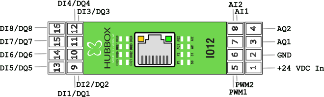
The terminal structure and electrical limits of the device are detailed below:
- Digital Input/Output (8 Channels - DIQ): Each channel can function as both an input and an output.
- Input Thresholds: Logic 0 < 7.3V | Logic 1 > 10.7V.
- Output: 24V switching capacity according to Smart High Side Switch(PNP) architecture.
- Analog Input (2 Channels - AI): 0-10V DC voltage reading. Provides a digital value between 0-4095 with 12-bit ADC resolution.
- Analog Output (2 Channels - AQ): 0-10V DC proportional voltage output. Used for valve positioning and speed reference.
- PWM Output (2 Channels): Precise frequency control from 1Hz up to 50kHz and 0-100% duty cycle.
2. Communication Configuration
Factory Default Settings:
• IP Address: 192.168.24.251
• Subnet Mask: 255.255.255.0
• Gateway: 192.168.24.254
• Modbus TCP Port: 502
• IP Address: 192.168.24.251
• Subnet Mask: 255.255.255.0
• Gateway: 192.168.24.254
• Modbus TCP Port: 502
Changing the IP Address
To adapt the device IP to your local network, use the following Holding Register addresses:
40004 - 40007: IP Address (e.g., for 192.168.1.100, write these octets sequentially to each register).40008 - 40011: Subnet Mask settings.
3. Detailed Modbus Register Map
The most critical addresses for data collection and control processes are listed below:
| Function | Register Address | Data Type | Access | Description |
|---|---|---|---|---|
| Digital Outputs | 1 - 8 | Coils (01) | R/W | Trigger Relay/Output (0: Off, 1: On) |
| Digital Inputs | 10001 - 10008 | Discrete (02) | Read | Field input signals |
| Analog Input 1-2 | 30001 - 30002 | Input (04) | Read | Raw data 0-4095 corresponding to 0-10V |
| PWM Frequency | 40027 | Holding (03) | R/W | Frequency value between 1Hz - 50,000Hz |
| PWM Duty Cycle | 40026 | Holding (03) | R/W | Percentage value between 0-100 |
| PWM Command | 40025 | Holding (03) | R/W | 1: Start, 2: Stop |
| Analog Output 1-2 | 40044 - 40045 | Holding (03) | R/W | 0-4095 range (for 0-10V output) |
4. Advanced Testing with Modbus Poll
- Connection: In Modbus Poll, go to
Connection > Connect. Enter192.168.24.251in the IP field. - Read Definition: Open the
Setup > Read/Write Definitionwindow.- For Analog data: Select Function
04 Input Register, Address0, Length10. - For Output control: Select Function
01 Read Coil.
- For Analog data: Select Function
5. Troubleshooting and Maintenance
Important: After configuring PWM and Analog Output values, remember that you must write "1" to the
PWMCmd (40025) register for the changes to take physical effect.- No Signal: Ensure that the GND line is common for the input terminals.
- No Communication: Check the Ethernet LEDs on the device. The yellow LED indicates data traffic, and the green LED indicates a link connection.
- Reset: Hold the Reset button on the device for 10 seconds to restore the device to its factory IP address
192.168.24.251.
HUBBOX Technical Support Team | www.hubbox.io/en/products/hubbox-io12-io-gateway