X2 4G/LTE Device setup
HUBBOX Connect X2 4G/LTE Installation and Connection Guide
Please follow the connection diagram and technical steps below to correctly complete the installation of your HUBBOX Connect X2 4G/LTE device.
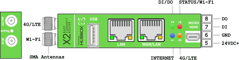
1. Device Interface and Connector Structure
The hardware interface consists of the following components:
- Antenna Inputs (SMA): Two SMA inputs on the far left for Wi-Fi and 4G/LTE antennas.
- USB Port: For external device integration or configuration.
- Ethernet Ports:
- LAN: Dedicated for local network/machine connection.
- WAN/LAN: Internet input or second local network port.
- Video Output: Micro HDMI port for monitor access.
- Micro SD Slot: Located at the back (DIN Rail section). Supports up to 256GB.
- SIM Card Slot: Located at the back (DIN Rail section). Designed for a Nano SIM card.
2. Power and I/O Connections
The terminal connections on the right side must be wired as follows:
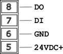
- Pin 8 (DO): Digital Output.
- Pin 7 (DI): Digital Input.
- Pin 6 (GND): Ground/Chassis connection (-).
- Pin 5 (24VDC+): Positive power input (+).
3. Status LED Indicators
Real-time system monitoring via four multi-colored LEDs:
- Green (DI / DO): Digital Input and Output activity.
- Red (Status): System status and Wi-Fi connection activity.
- Blue (Internet): Successful cloud/internet access.
- Orange (4G/LTE): Cellular connection status (Simcom module).
4. 4G/LTE Specific Installation Instructions
Note: This model is equipped with a high-performance 4G/LTE module. Signal optimization is critical for remote access stability.
SIM and SD Card Installation
- Location: The combo slot is in the internal compartment at the back, behind the DIN Rail bracket.
- Nano SIM: Ensure power is OFF before insertion. Follow the orientation guide on the PCB.
- SD Card: Use high-quality Micro SD cards for reliable log recording.
Antenna & Signal Optimization
- Connection: Mount the high-gain LTE antenna to the designated SMA input.
- Metal Cabinets: If the device is inside a metal enclosure (Faraday cage), you must use an external wired magnetic antenna moved outside the cabinet.
- Tightening: SMA connectors should be hand-tightened firmly. Loose connections cause signal loss and module overheating.
Status Verification (Orange LED)
- Flashing: Searching for network or validating SIM.
- Steady ON: 4G/LTE connection established and ready for data traffic.
5. Technical Specifications Table
| Feature | Description / Supported Bands |
|---|---|
| Network Technology | LTE Cat-4, HSPA+, UMTS |
| LTE-FDD Bands | B1, B3, B5, B7, B8, B20 |
| Max DL / UL Speed | 150 Mbps Download / 50 Mbps Upload |
| SIM Interface | 1.8V / 3.0V (Nano SIM) |
| Operating Temp | -40°C to +85°C |
6. Final Installation Steps
- Power: Connect 24V DC to Pin 5(+) and Pin 6(-).
- 4G/LTE Setup: Insert SIM card. Access the Local Panel > Mobile Settings to enter APN and PIN.
- Wi-Fi Access: To use the factory "hbbx" profile, set your router SSID to
hbbxand password to the device Serial Number. - Verification: A steady Blue LED confirms the device is online and reachable.
Management Access:
Default IP:
Credentials:
Default IP:
192.168.24.254Credentials:
hubbox / hubboxHUBBOX Technical Support | www.hubbox.io