IOR4 Device setup
HUBBOX IOR4 Relay Controller: Detailed User Manual
HUBBOX IOR4 is a Modbus TCP relay module optimized for controlling high-current loads and monitoring digital signals in industrial environments. With 4 relay outputs (5A capacity) and 4 digital inputs, it offers a compact and reliable I/O expansion solution.
1. Hardware Features and Connection Structure
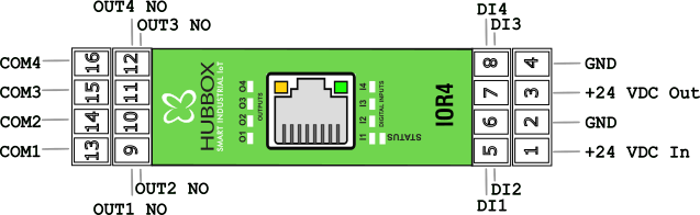
Electrical connections and terminal layout are critical for the safe operation of the device:
- Relay Outputs (4 Channels - DO): Normally Open (NO) contacts capable of switching up to 5A at 220VAC or 30VDC.
- Digital Inputs (4 Channels - DI): Dry contact or voltage inputs with threshold values of Logic 0 < 7.3V and Logic 1 > 10.7V.
- Power Supply: Wide operating voltage range between 12-35V DC.
- Isolation: Circuit design with high isolation against industrial noise.
2. Network and Communication Settings
Default Factory Settings:
• IP Address: 192.168.24.251
• Subnet Mask: 255.255.255.0
• Gateway: 192.168.24.254
• Modbus TCP Port: 502
• IP Address: 192.168.24.251
• Subnet Mask: 255.255.255.0
• Gateway: 192.168.24.254
• Modbus TCP Port: 502
Network Configuration (Holding Registers)
To change the network settings of the device, write operations must be performed to the following register addresses:
40004 - 40007: IP Address (Octet-based).40008 - 40011: Subnet Mask settings.40012 - 40015: Gateway address definition.
3. Detailed Modbus Register Table
The register map used to access all inputs and outputs on the HUBBOX IOR4:
| Function | Register Address | Data Type | Access | Description |
|---|---|---|---|---|
| Relay Outputs | 1 - 4 | Coils (01) | R/W | Out1 - Out4 (1: Active, 0: Passive) |
| Digital Inputs | 10001 - 10004 | Discrete (02) | Read | Input1 - Input4 Status |
| Uptime Counter | 30006 - 30007 | Input Reg. (04) | Read | Device operating time (Seconds) |
| Device Serial No | 30013 - 30018 | Input Reg. (04) | Read | Unique hardware identification |
| Relay Safety Mode | 40019 | Holding (03) | R/W | Relay state upon communication loss |
4. Testing and Commissioning with Modbus Poll
- Power the device and connect it to your network via an Ethernet cable.
- In the Modbus Poll software, select Modbus TCP/IP from the Connection > Connect menu and connect to the address
192.168.24.251. - In the Setup > Read/Write Definition tab:
- To control the relays, select
01 Coil Status. - To monitor inputs, select
02 Input Status.
- To control the relays, select
5. Safety and Maintenance Recommendations
Important Warning: When controlling inductive loads (solenoid valves, motors, etc.), an RC snubber or diode must be used to protect the relay contacts from arcing.
- Troubleshooting: If the Status LED on the device is flashing, it means communication is active. Relay LEDs indicate the physical state of the output.
- Resetting: If the IP address is forgotten, you can restore the device to default factory settings by holding the Reset button for 10 seconds.
- Mounting: Ensure the device is securely seated on the DIN rail and that terminal screws are tight.
For inquiries: www.hubbox.io/en/products/hubbox-ior4-relay-controller | HUBBOX Support Center